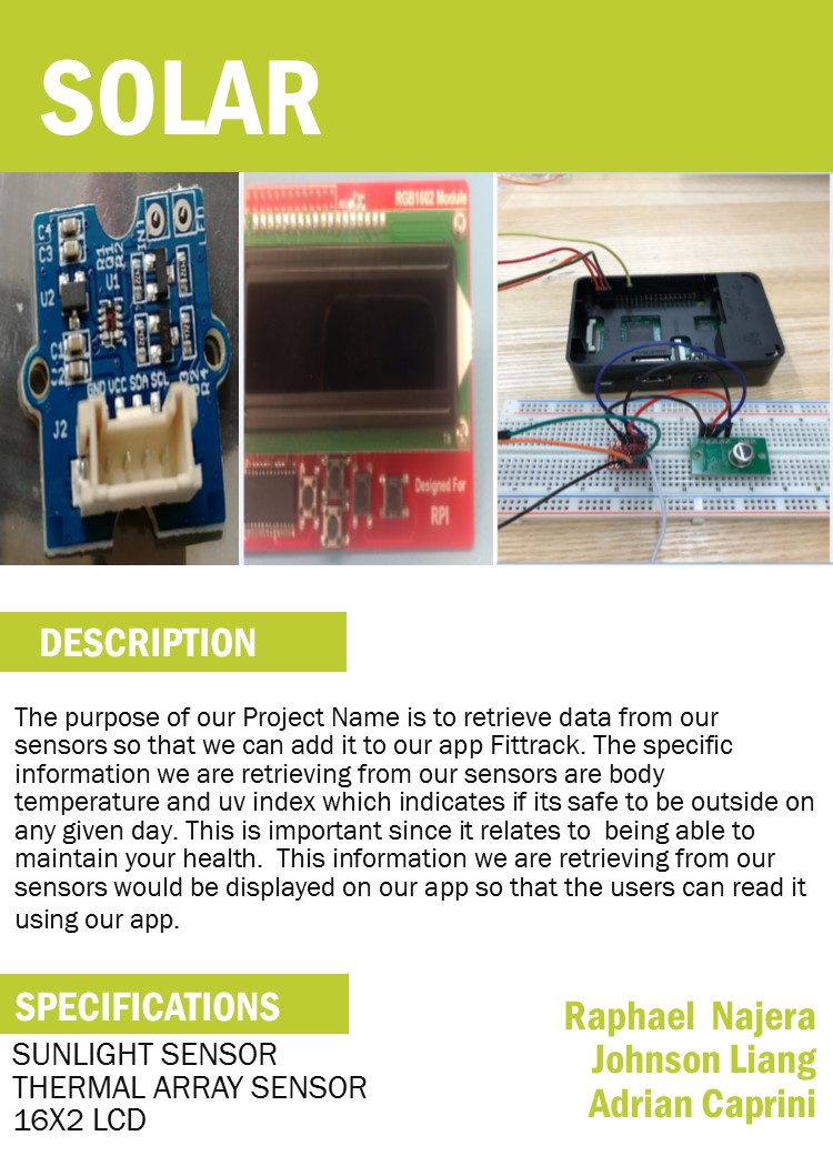
Sunlight_Sensor
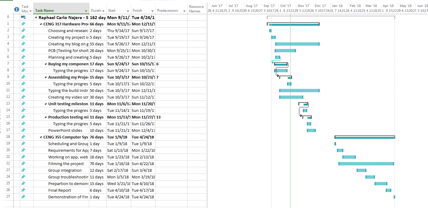
CENG 355 Solar Capstone Project Blog.
Solar Capstone Web App
Week 13 April 23, 2018
Week 12 April 16, 2018
Week 11 April 9, 2018
- Today we demonstrated our work to Austin
Week 10 April 2, 2018
- Since last week we have added a image to the main screen, a splash screen and an about page to the mobile application.
- In the python script we added the code to push the data from PV3 to our firebase
- Submitted the Status Report C
- Updated the Technical Report to include the Status Report C.
Week 9 March 26, 2018
- Submitted the technical report checklist and Conclusion. From the submitted document it appears that we are on track.
- Since last week we have added the history log for PV1, PV2, and PV4. The logs will display the last 11 entries from Firebase of each table.
- We also added code into the python script which we expect to delete all entries from the table every 30 days.
- Updated the Technical Report to include the Conclusion
Week 8 March 19, 2018
- Submitted the Status Report B
- Added the history/log to our mobile and web application
- Updated the Technical Report to include the Status Report B
Week 7 March 12, 2018
- Submitted the build instructions
- We were able to retrieve data in our applications with the data pushed on Firebase. Our mobile and web application now retrieves the latest query and displays it for user to observe.
- Solar Capstone Web App
- Python script now pushes the epoch time to Firebase, which will be used later on to delete data entries (up to 30 days).
- Starting to work on the status report B thats due next week
- Updated our SRS with the feedback given
- Combined the build instructions and status report A into our final technical report Technical Report v2
Week 6 March 5, 2018
- Submitted the Status Report A
- We continued to work on the python code and was able to retrieve data from PV2
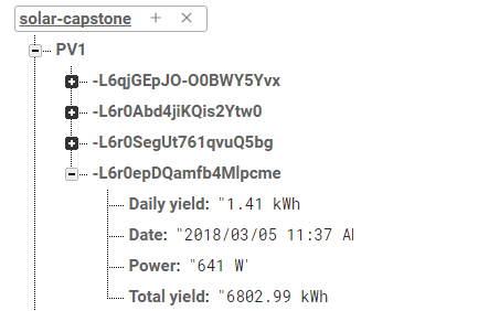
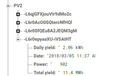
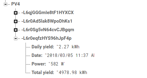
- We tested Firebase code to connect and push the data retrieved from all three solar panels. As a result, our current database stores data from the following fields: date (timestamp), power, daily and total energy yield.
- Below the following screen-shot displays the result of our code, including PV2.
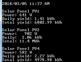
- Screen-shots of our Firebase
- PV1
- PV2
- PV4
Week 5 February 26, 2018
- Submitted the Abstract, Introduction, and Declaration of authorship documents
- Additionally, we fixed our SRS and our technical report to match the OACETT requirements.
Week 4 February 19, 2018
- During the week of Family Day we focused on learning Python to retrieve data from the corresponding IP address to their PV. As a result, we were successfully able to retrieve the power, total yield, and daily yield fields from PV1 and PV4.
- Below the following screen-shot displays the result of our code.

Week 3 February 12, 2018
- Submitted the SRS (requirements specification)
- We started creating the mobile application, database, and web application. Furthermore, we have decided that the mobile app will be created using Android Studios, the database will be created using Firebase, and the web application will be created using NetBeans.
- Raphael is working on the mobile application, Adrian is working on the database and Johnson is working on the web application.
Week 2 February 5, 2018
- Submitted the Project Content and Project Proposal
- Creating the SRS (requirements specification)
- We visited room L240 to have a better understanding of the school’s Solar system. We observed that all PV panels were set up except PV3.
- Updated our Placard to our current project

Week 1 January 29, 2018
- Group: Raphael Najera, Johnson Liang, and Adrian Caprini
- Next step is to work on the Proposal
- The name of the project our group is working on is called Solar Capstone. Will be using the Solar Panels to read data and store it in the database.
Raphael Najera CENG 317 Sunlight Sensor Blog.
Week 12 January 22, 2018
Week 11 January 15, 2018
Week 10 January 8, 2018
-
Progress Report: Sunlight Sensor
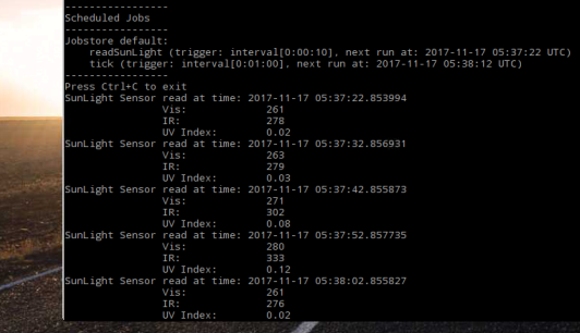
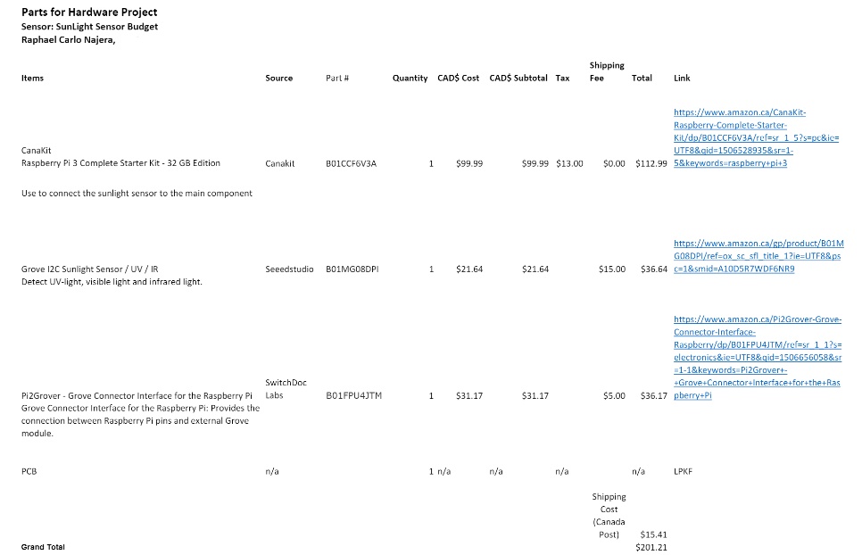
The recent project activities I did for my hardware project are, I first choose my sensor that I will be working on which was the sunlight sensor. So far, I wrote the proposal, project schedule and budget. I have acquired the main hardware components needed for my project. The hardware components that I have acquired is raspberry pi, sunlight sensor and Connector Interface. In my project schedule this would completed the ID 6 Buying my components/parts. I also research on setting up my raspberry pi and connected my sunlight sensor to the connector interface on the raspberry pi. After that, I tested the code and I was able to get the data from the sunlight sensor of Visible light (Vis), Infrared light (IR) and UV – Light (UV Index). I also recorded the 30 second build video of unboxing the parts, connecting the part and powering up. On my project schedule I have completed id 9 to 13.
The current progress in meeting the objectives of the project is going well. I have received the required components to build my project and then tested the sensor. On Jan 8, I demonstration my sensor to the professor. I was able to retrieve the data from the sunlight sensor. The next objective is to write the build instruction and PowerPoint for the presentation.
The problem I encounter when setting up the sunlight sensor to work with the raspberry pi was I had some problem on running the code to retrieve data from the sunlight sensor. When I first run the code, it output an error “ImportError: No module named Adafruit_PureIo.smbus”. I found out I had missing files. On the website I found there was a fix to the error. I had to clone “ https://github.com/adafruit/Adafruit_Python_PureIO.git” and “sudo python setup.py install” which will add the missing module Adafruit_Purelo.smbus to fix the error. After I install setup.py I was able to run the code successfully and was able to display the data from the sunlight sensor.
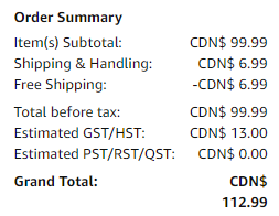
As of right now the projects financial update is currently still in budget. I believe there no reasons that I will exceed my budget as all my hardware and component needed has been acquired.
- Link to GitHub: https://github.com/RaphaelNajera/Sunlight_Sensor
- Link to Code: https://github.com/RaphaelNajera/Sunlight_Sensor/tree/master/firmware
Week 9 December 18, 2017
- 30 second build video
Week 8 December 11, 2017
- 30 second build script
In my 30 second video it will include an opening title screen, showing the parts, the parts connected to the raspberry pi, testing and showing the output.
Opening:
- Displaying my name and the sensor I’m using to build for my Hardware project.
Showing the parts:
- “The parts I’m using to build are raspberry pi, sunlight sensor and Connector Interface.”
- Showing the pictures of the parts required for my Hardware project.
Part assembly:
- Showing how to connection the sunlight sensor with the connector interface to the raspberry pi.
Powering up:
- Showing the raspberry pi powered up and the code running.
- “The functionality I plan to demonstrate is the sunlight sensor will read the data of Vis (visible light), IR (infrared light) and UV Index (UV-Light) and the code will display the data on the raspberry pi”
Week 7 December 4, 2017
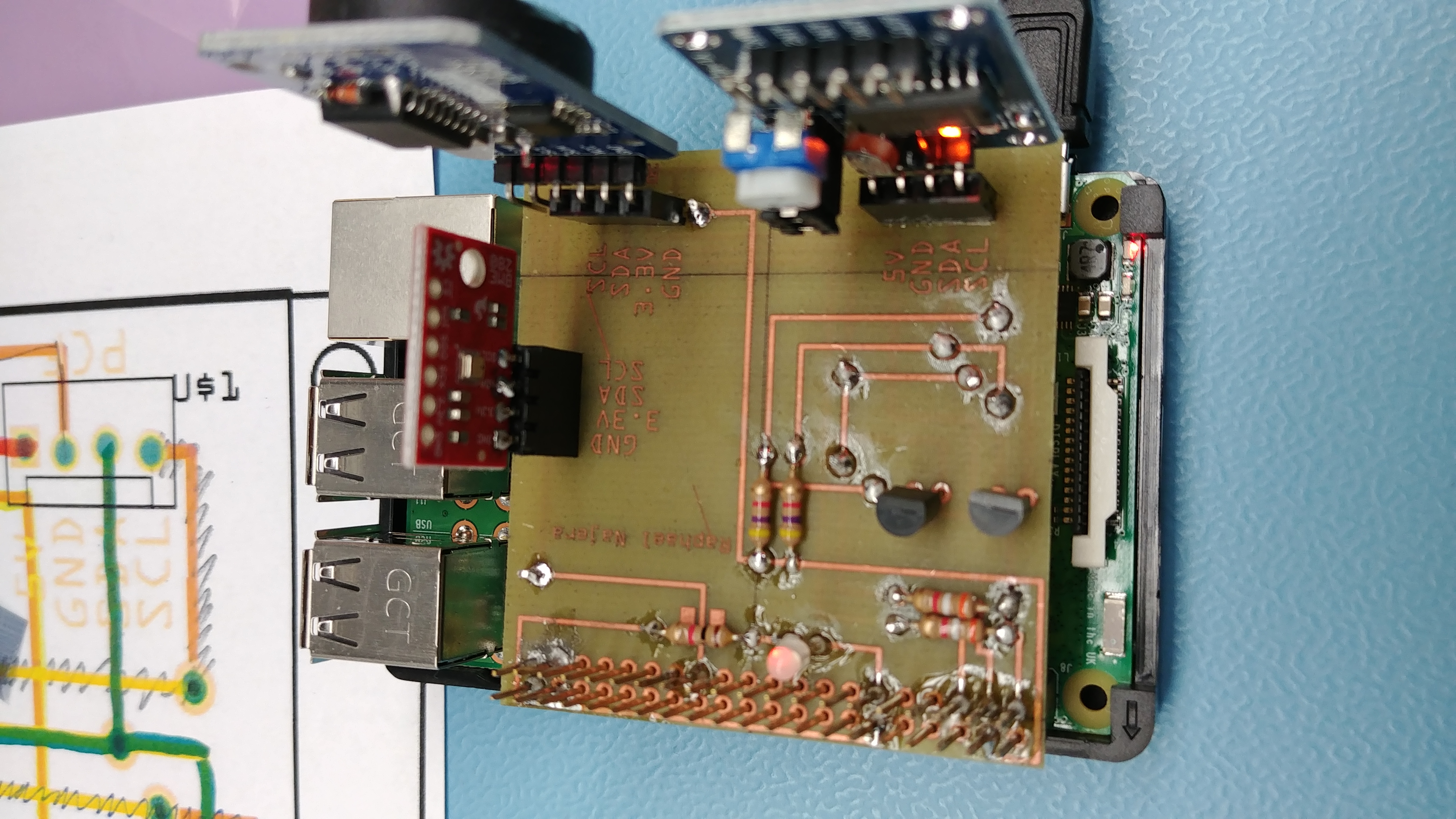
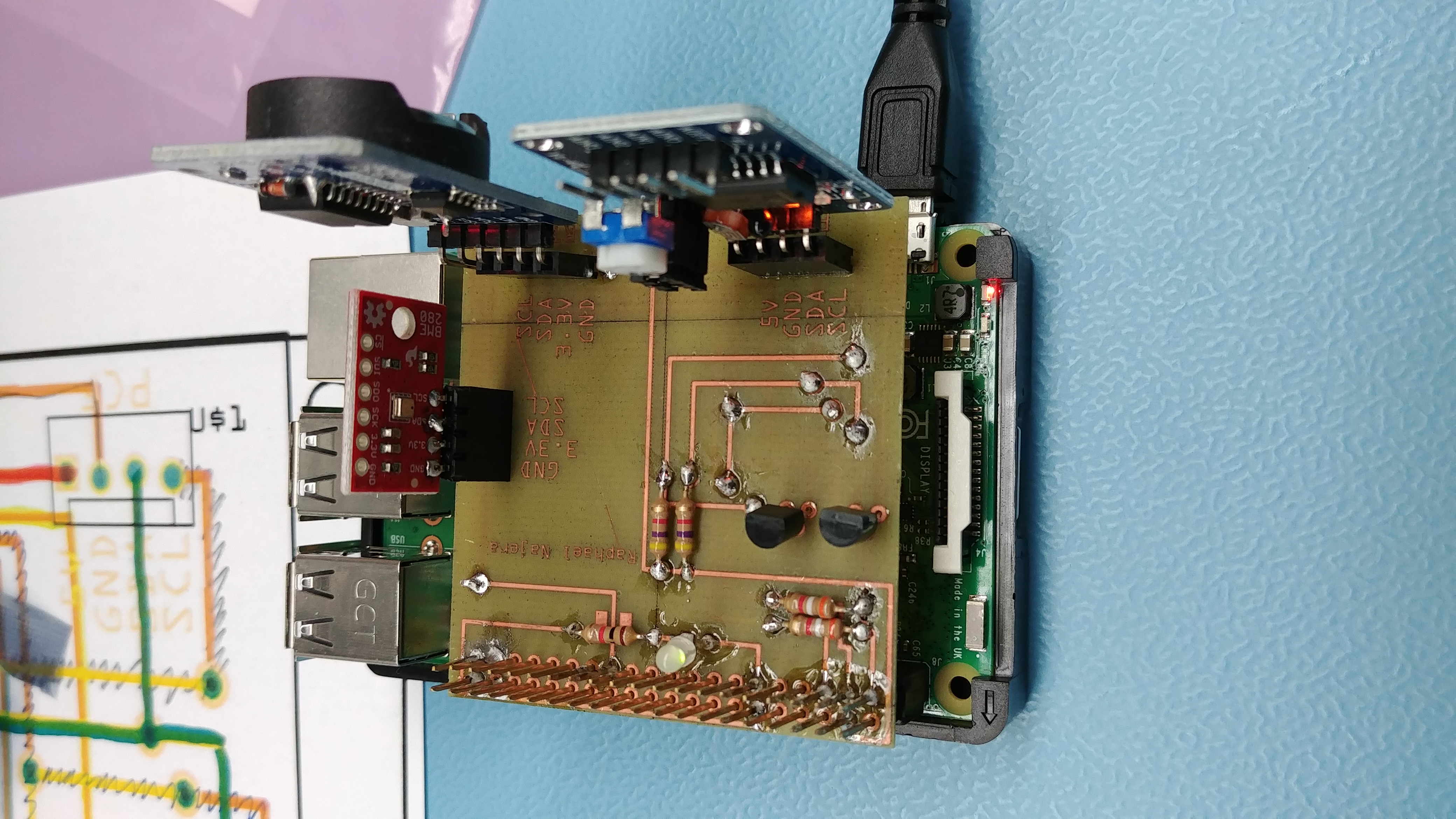
- Today in class I tested my StudentSenseHat before I test my studentsensehat I had to cut the trace near IC1. I tested the blinked LED by running traffic2B.c. on the StudentSenseHat the LED blink from Red to Green.
- StudentSenseHat
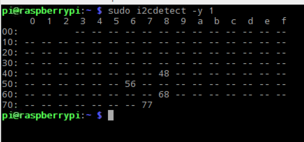
- Checking the sensor is connected by typing sudo i2cdetect -y 1
- Blinking LED
- Red light
- Green light
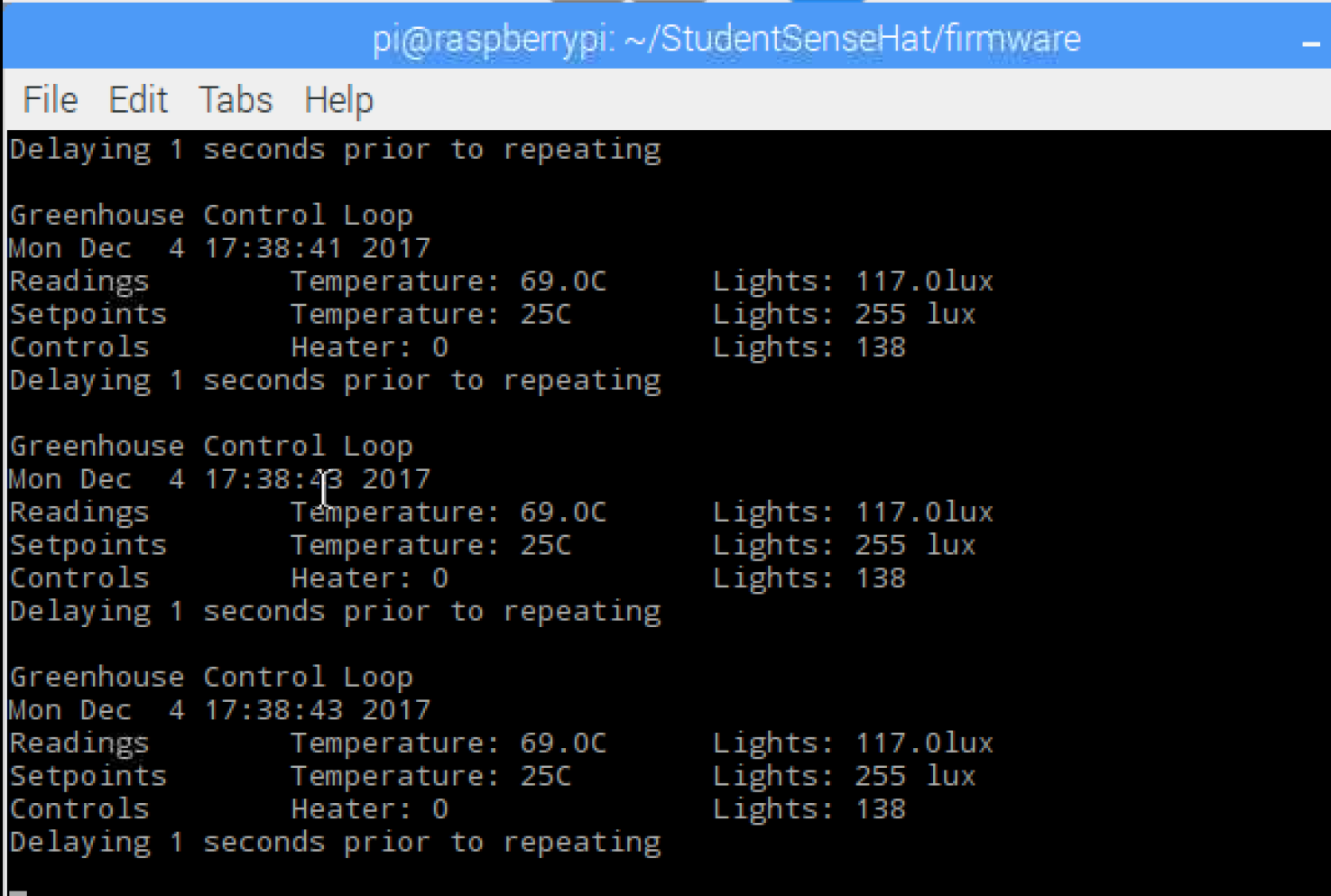
- Testing ghmain. It display the reading from the sensor
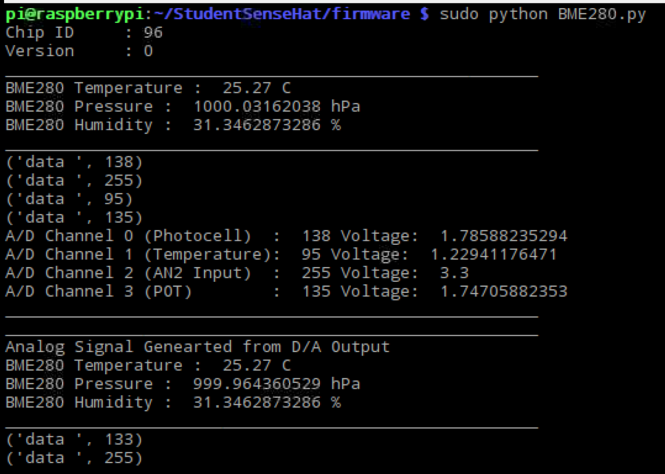
- Testing BME280.
Week 6 (October 16, 2017 - November 27, 2017)
During the Past 5 Weeks the school was on strike. This is what I worked on during the strike:
-
Started reading the build guide on how to connect my sensor to my raspberry pi.
- I enable the I2C Bus in my raspberry pi 3 to allow the sensor to connect to the Raspberry Pi. I also blinked the LED on my raspberry pi 3.
-
I received the module that I was missing to complete the Student Sense Hat from the prototype lab on the week of October 30, 2017
- I Connected the sunlight sensor to my raspberry pi 3 and Filmed the part assembly for my build video
- I set up the code for the sunlight sensor to test. It prints out Vis (visible light), IR (infrared light) and UV Index (UV-Light)
- Output of testing the Sunlight Sensor:
- Adding the modules to my Student Sense Hat
On Week 5 October 16, 2017
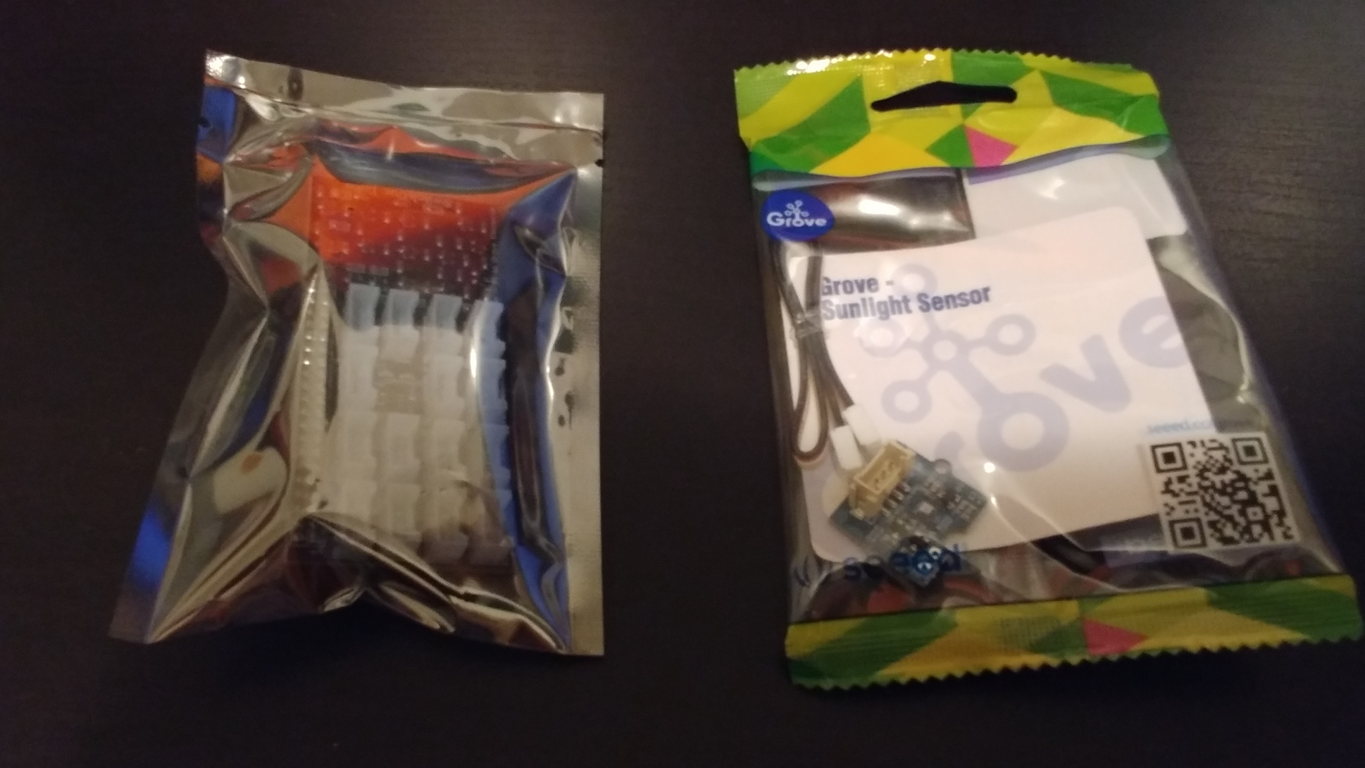
- I have acquired the components needed for my project. The hardware components that I have acquired is raspberry pi, sunlight sensor and Pi2Grover - Grove Connector Interface. I am ready to start building my project.
- Grove Connector Interface and Sunlight Sensor
- Watched videos on how to solder.
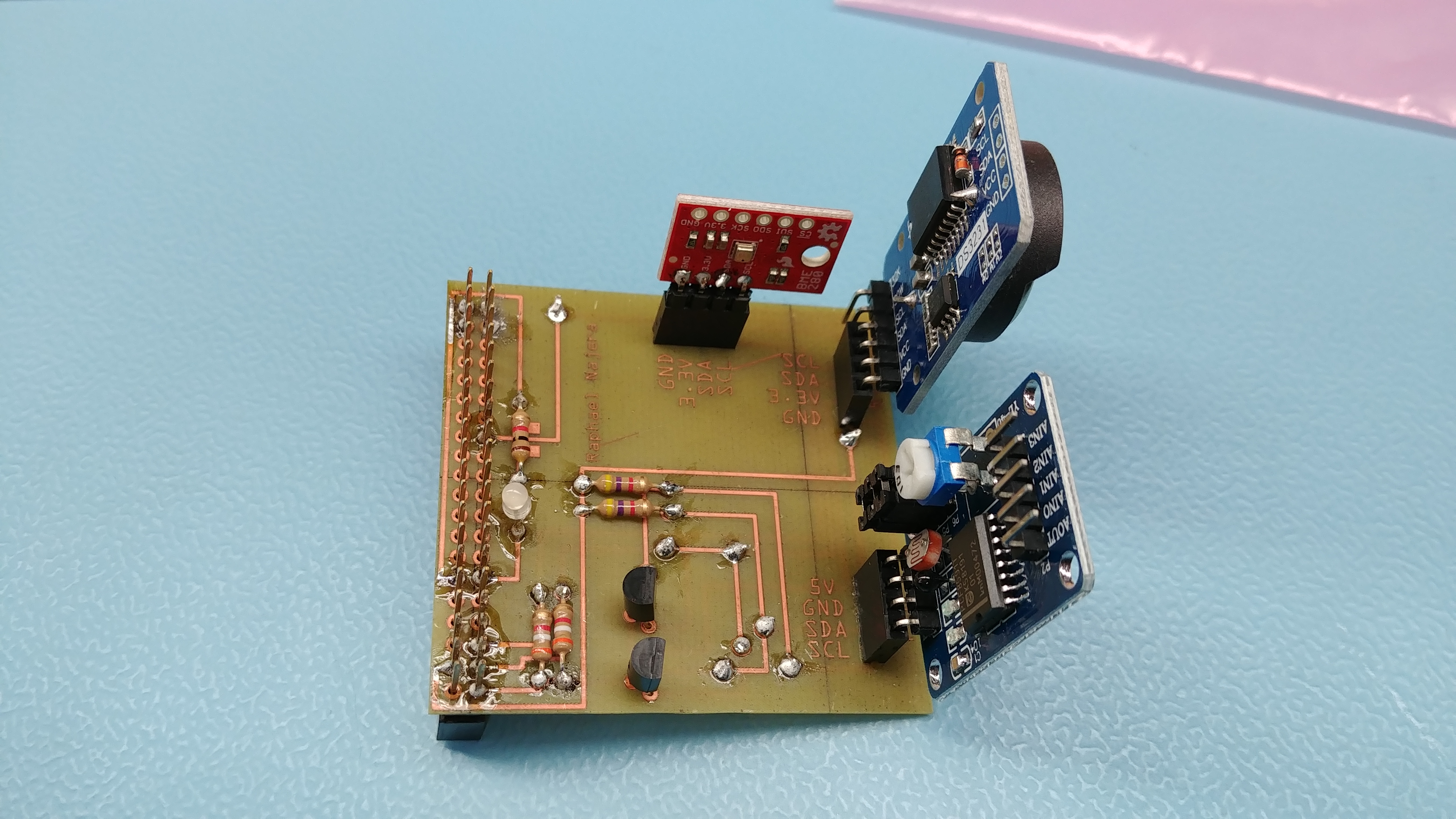
- On Wednesday October 18, I went to the prototype lab to solder my PCB board for the student sense hat. As of right now I have completed soldering for the PCB board. I’m now missing the module need to complete the student sense hat. The next step is to test the PCB board to see if it will power up.
Week 4 October 2, 2017
- I Submitted my Budget Plan
- During the weekend I started to buy the parts needed for my project.
- During class I also tried to test out the Raspberry pi lab testing the light blinking but I wasn’t able to connect the Raspberry pi to the computer. I followed the step but got into a problem when connecting to the raspberry pi. I use Raspberry pi #153 from the part crib.
- After class I received the PCB board and parts kit for the Student Sense Hat from Kelly at the prototype lab. The next step is I have to solder the component to the PCB board.
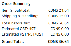
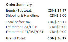
- Recived the Grove I2C Sunlight Sensor / UV / IR and Pi2Grover - Grove Connector Interface for the Raspberry Pi on October 12.
- Grove I2C Sunlight Sensor / UV / IR 3 Receipt
- Grove Connector Interface for the Raspberry Pi Receipt
Week 3 September 25, 2017
- During class I submitted my Schedule Plan
- The next step is to create my Budget Plan which will help me decide how much I would spend on my project. I already ordered my Raspberry Pi 3.
- The next part is to ordered Grove I2C Sunlight Sensor / UV / IR and Pi2Grover - Grove Connector Interface for the Raspberry Pi. I orderd these parts on October 1.
Week 2 September 18, 2017
- I submitted my Proposal
- The next step is to start on creating my schedule plan which is due on Week 3.
- I ordered the Raspberry Pi 3 on amazon on September 20,2017 and recived the Raspberry Pi 3 on September 21, 2017.
- Raspberry Pi 3 Receipt
- I Used the program called fritzing to add my name to the PCB board. I then sent an email attched with the gerber files to vlad/kelly to request for the PCB board.
Week 1 September 11,2017
- I created my repository and choose the sensor that I will be building with for my IoT Hardware project.
- The sensor I choose is Sunlight sensor.
- I started to research about the sunlight sensor and build guide on what to build with the sunlight sensor which will help me on creating my proposal that is due next week.